Product Description
HangZhou QY Precision Co., Ltd
QY Precision specializes in design and production of high precision metal parts and components. Focus on industry and action on demand, to be your trusted partner is our mission.
Detailed Photos
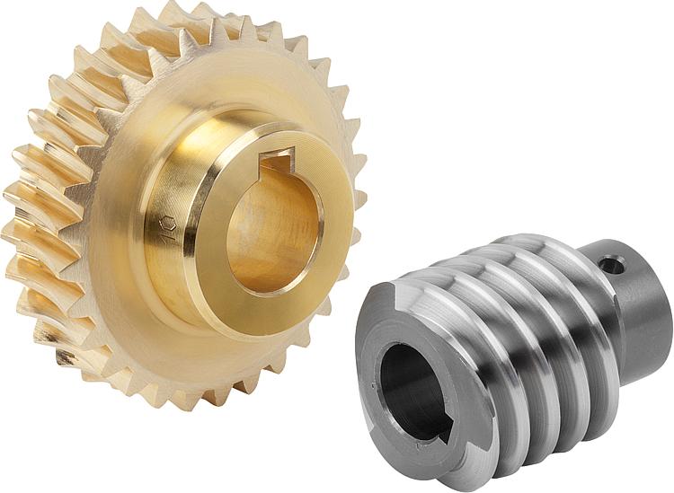
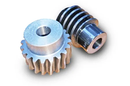
Custom Worm Gear Curved Hard Tooth Surface Stainless Steel Worm Gear
Product Description
Gear Introduction
Bevel Gears
Bevel gears are most commonly used to transmit power between shafts that intersect at a 90 degree angle. They are used in applications where a right angle gear drive is required. Bevel gears are generally more costly and are not able to transmit as much torque, per size, as a parallel shaft arrangement.
Worm Gear
Worm gears transmit power through right angles on non-intersecting shafts. Worm gears produce thrust load and are good for high shock load applications but offer very low efficiency in comparison to the other gears. Due to this low efficiency, they are often used in lower horsepower applications.
Helical Gears
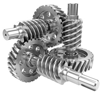
Helical gears have teeth that are oriented at an angle to the shaft, unlike spur gears which are parallel. This causes more than 1 tooth to be in contact during operation and helical gears can carry more load than spur gears. Due to the load sharing between teeth, this arrangement also allows helical gears to operate smoother and quieter than spur gears. Helical gears produce a thrust load during operation which needs to be considered when they are used. Most enclosed gear drives use helical gears.
Spur Gears
Spur gears transmit power through shafts that are parallel. The teeth of the spur gears are parallel to the shaft axis. This causes the gears to produce radial reaction loads on the shaft, but not axial loads. Spur gears tend to be noisier than helical gears because they operate with a single line of contact between teeth. While the teeth are rolling through mesh, they roll off of contact with 1 tooth and accelerate to contact with the next tooth. This is different than helical gears, which have more than 1 tooth in contact and transmit torque more smoothly.
Hypoid Gears
Hypoid gears look very much like a spiral bevel gear, but unlike spiral bevel gears, they operate on shafts which do not intersect. In the hypoid arrangement because the pinion is set on a different plane than the gear, the shafts are supported by the bearings on either end of the shaft.
Herringbone Gears
Herringbone gears are very similar to the double helical gear, but they do not have a gap separating the 2 helical faces. Herringbone gears are typically smaller than the comparable double helical and are ideally suited for high shock and vibration applications. Herringbone gearing is not used very often due to their manufacturing difficulties and high cost.
Specification:
| Services | CNC Milling, CNC Turning, Wire EDM Cutting, 3D Printing,Vacuum Casting,Reaction Injection Molding, Plastic CNC Machining, Laser, Cutting, Stamping Parts, Bending Parts |
| Material | Metal: Aluminum , Copper , Brass , Steel, Stainless Steel, Titanium and etc. |
| Plastic: ABS, POM, PP, PU, PC,PA66, PMMA, PVC, PVE, Nylon and etc. | |
| Surface treatment | Anodizing, Sandblasting, Metal Plating, Polishing, Painting, Powder coating, Brushing ,Silk-screen , Laser Engraving etc. |
| Heat treatment | Annealing, Normalizing , Nitriding, Tempering |
| File Formats | STP, STEP, IGS,STP,X_T ,DXF,DWG , Pro/E, PDF, SLDPRT |
| Inspection | In-house or third party, all the products are strictly inspected by skilled QC |
| Service Type | OEM & ODM Service |
Surface Finish:
Available Material:
FAQ
1.How to get a quote?
Kindly send us the drawing of your product,please. Including details as below: a.Materials b. Surface Finish c. Tolerance d. Quantity If you need solutions for your application, kindly send us your detail requirements, and we will have engineers to service you.
2.How does the payment process work?
Payment terms are flexible for us. We can accept different type payment way.
3.How do I know about the production?
We will double confirm your requirements and send you the sample before the mass production as you required. During the mass production,
4.How do I know about the delivery?
Before shipment we will confirm with you about all the details including CI and other attention issues. After ship out, we will inform you of the tracking number and keep updating the latest shipping information for you.
5.What will you do for after sales?
We will follow up and await your feedback. Any question related to our metal parts, our experienced engineers are ready to help. And welcome to contact for any supporting of your other application even if their is no relationship with our products.
Packaging & Shipping
| Application: | Fastener, Auto and Motorcycle Accessory, Hardware Tool, Machinery Accessory, Robotics |
|---|---|
| Standard: | GB, EN, API650, China GB Code, JIS Code, TEMA, ASME, CE, FCC, RoHS, ISO9001:2008 |
| Surface Treatment: | Anodizing |
| Samples: |
US$ 0/Piece
1 Piece(Min.Order) | Order Sample |
|---|
| Customization: |
Available
| Customized Request |
|---|
.shipping-cost-tm .tm-status-off{background: none;padding:0;color: #1470cc}
|
Shipping Cost:
Estimated freight per unit. |
about shipping cost and estimated delivery time. |
|---|
| Payment Method: |
|
|---|---|
|
Initial Payment Full Payment |
| Currency: | US$ |
|---|
| Return&refunds: | You can apply for a refund up to 30 days after receipt of the products. |
|---|

Are worm gears suitable for high-torque applications?
Worm gears are indeed well-suited for high-torque applications. Here's a detailed explanation of why worm gears are suitable for high-torque applications:
Worm gears are known for their ability to provide significant speed reduction and torque multiplication. They consist of a threaded cylindrical gear, called the worm, and a toothed wheel, called the worm wheel or worm gear. The interaction between the worm and the worm wheel enables the transmission of motion and torque.
Here are the reasons why worm gears are suitable for high-torque applications:
- High gear reduction ratio: Worm gears offer high gear reduction ratios, typically ranging from 20:1 to 300:1 or even higher. The large reduction ratio allows for a significant decrease in rotational speed while multiplying the torque output. This makes worm gears effective in applications that require high levels of torque.
- Self-locking capability: Worm gears possess a unique self-locking property, which means they can hold position and prevent backdriving without the need for additional braking mechanisms. The angle of the worm thread creates a mechanical advantage that resists reverse rotation of the worm wheel, providing excellent self-locking characteristics. This self-locking capability makes worm gears ideal for applications where holding the load in place is crucial, such as in lifting and hoisting equipment.
- Sturdy and robust design: Worm gears are typically constructed with durable materials, such as steel or bronze, which offer high strength and resistance to wear. This robust design enables them to handle heavy loads and transmit substantial torque without compromising their performance or longevity.
- High shock-load resistance: Worm gears exhibit good resistance to shock loads, which are sudden or intermittent loads that exceed the normal operating conditions. The sliding contact between the worm and the worm wheel teeth allows for some degree of shock absorption, making worm gears suitable for applications that involve frequent or unexpected high-torque impacts.
- Compact and space-efficient: Worm gears have a compact design, making them space-efficient and suitable for applications where size is a constraint. The compactness of worm gears allows for easy integration into machinery and equipment, even when there are spatial limitations.
It's important to consider that while worm gears excel in high-torque applications, they may not be suitable for high-speed applications. The sliding contact between the worm and the worm wheel generates friction, which can lead to heat generation and reduced efficiency at high speeds. Therefore, worm gears are typically preferred in low to moderate speed applications where high torque output is required.
When selecting a worm gear for a high-torque application, it's important to consider the specific torque requirements, operating conditions, and any additional factors such as speed, efficiency, and positional stability. Proper sizing, lubrication, and maintenance are also crucial to ensure optimal performance and longevity in high-torque applications.

How do you calculate the efficiency of a worm gear?
Calculating the efficiency of a worm gear involves analyzing the power losses that occur during its operation. Here's a detailed explanation of the process:
The efficiency of a worm gear system is defined as the ratio of output power to input power. In other words, it represents the percentage of power that is successfully transmitted from the input (worm) to the output (worm wheel) without significant losses. To calculate the efficiency, the following steps are typically followed:
- Measure input power: Measure the input power to the worm gear system. This can be done by using a power meter or by measuring the input torque and rotational speed of the worm shaft. The input power is usually denoted as Pin.
- Measure output power: Measure the output power from the worm gear system. This can be done by measuring the output torque and rotational speed of the worm wheel. The output power is usually denoted as Pout.
- Calculate power losses: Determine the power losses that occur within the worm gear system. These losses can be classified into various categories, including:
- Mechanical losses: These losses occur due to friction between the gear teeth, sliding contact, and other mechanical components. They can be estimated based on factors such as gear design, materials, lubrication, and manufacturing quality.
- Bearing losses: Worm gears typically incorporate bearings to support the shafts and reduce friction. Bearing losses can be estimated based on the bearing type, size, and operating conditions.
- Lubrication losses: Inadequate lubrication or inefficient lubricant distribution can result in additional losses. Proper lubrication selection and maintenance are essential to minimize these losses.
- Calculate efficiency: Once the power losses are determined, the efficiency can be calculated using the following formula:
Efficiency = (Pout / Pin) * 100%
The efficiency is expressed as a percentage, indicating the proportion of input power that is successfully transmitted to the output. A higher efficiency value indicates a more efficient gear system with fewer losses.
It is important to note that the efficiency of a worm gear can vary depending on factors such as gear design, materials, lubrication, operating conditions, and manufacturing quality. Additionally, the efficiency may also change at different operating speeds or torque levels. Therefore, it is advisable to consider these factors and conduct efficiency calculations based on specific gear system parameters and operating conditions.

How do you install a worm gear system?
Installing a worm gear system requires careful attention to ensure proper alignment, lubrication, and secure mounting. Here are the general steps involved in installing a worm gear system:
- Prepare the components: Before installation, ensure that all the components of the worm gear system, including the worm, worm wheel, bearings, and housing, are clean and free from any contaminants or damage. Inspect the components for any signs of wear or defects.
- Check alignment: Verify that the mating surfaces of the worm and worm wheel are clean and free from any debris. Ensure that the gear teeth mesh properly and that there is no excessive backlash or misalignment. Make any necessary adjustments or repairs before proceeding with the installation.
- Apply lubrication: Lubricate the worm gear system according to the manufacturer's recommendations. Select a suitable lubricant that provides sufficient lubrication and reduces friction between the worm and worm wheel during operation. Apply the lubricant evenly to the gear teeth and other contact surfaces.
- Mounting: Position the worm gear system in the desired location, taking into account any space constraints or mounting requirements. Use appropriate fasteners, such as bolts or screws, to securely attach the system to the surrounding structure or base. Ensure that the mounting surfaces are clean, flat, and able to withstand the forces and loads exerted by the gear system.
- Alignment and adjustment: Once the worm gear system is mounted, check the alignment again and make any necessary adjustments. Ensure that the worm and worm wheel are properly engaged and that there is no excessive play or binding. Pay attention to any specified alignment tolerances provided by the manufacturer.
- Testing and operation: After installation, conduct a thorough functional test of the worm gear system. Verify that it operates smoothly, without unusual noise or vibration. Check for proper engagement of the gear teeth and ensure that the system performs as intended under different load conditions. Monitor the system's performance during initial operation and address any issues or abnormalities promptly.
It's important to follow the specific installation instructions provided by the gear system manufacturer. Different worm gear designs and applications may have additional installation requirements or considerations that should be taken into account.
Proper installation of a worm gear system ensures its reliable operation, minimizes wear, and maximizes its lifespan. If you are unsure about any aspect of the installation process, it is recommended to consult the manufacturer or seek the assistance of a qualified professional.


editor by CX 2023-10-16